Grade 12 Physical Sciences · Electricity and Magnetism
Describe generators and motors
Describe how generators and motors work, their energy changes and parts like slip rings, commutators and brushes (a motor changes electrical to mechanical energy).
- past paper questions use it
- 23 past paper questions use it
- videos
- 3 videos
Learn it: describe generators and motors
Pick one and watch it, then try the questions below. Videos load only when you tap play.
Now try it on a real exam question
No sign-up. Takes 3 minutes.
Question 1.9 · November 2025 · Paper 1 · National (DBE) · 2 marks
Work it out on paper first. Then mark yourself with the official memo, one tick at a time.
More past paper questions: describe generators and motors
Work each one out first, then open the memo and check every tick.
3. Question 9.1.3 · May/June 2025 · Paper 1 · National (DBE) · 3 marks
9.1 The diagram below represents a simplified version of an AC generator.
The induced current flows from X to Y in the coil when the coil is rotated clockwise, as shown in the diagram below.
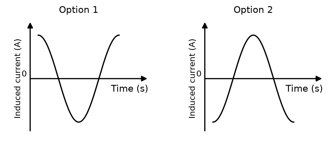
Answer the questions that follow.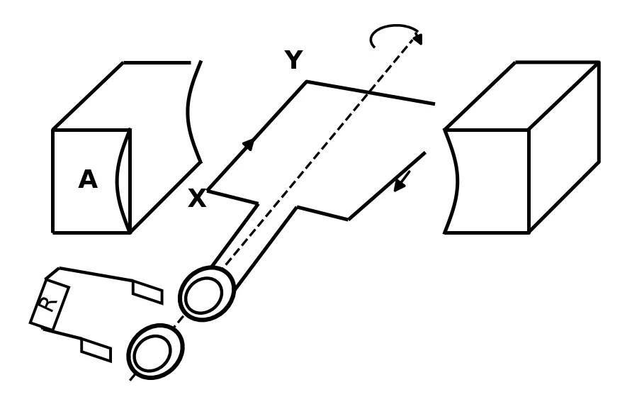 9.1.3 Sketch a graph of induced current versus time for ONE complete rotation of the coil from the horizontal position, as shown in the diagram above.(3)
Show the memo (3 ticks)Memo
- ✓Starts at maximum currentThe AC graph starts with maximum current (positive or negative maximum) at .
1 mark · Describe generators and motors
- ✓One complete cycleThe graph is drawn for one cycle / one complete wavelength.
1 mark · Describe generators and motors
- ✓Correct shapeCorrect shape: a cosine graph.
1 mark · Describe generators and motors
- ✓
4. Question 9.4 · November 2025 · Paper 1 · National (DBE) · 3 marks
An AC generator operates a fan. The directions of the rotation of the coil and the induced current are shown in the simplified diagram below.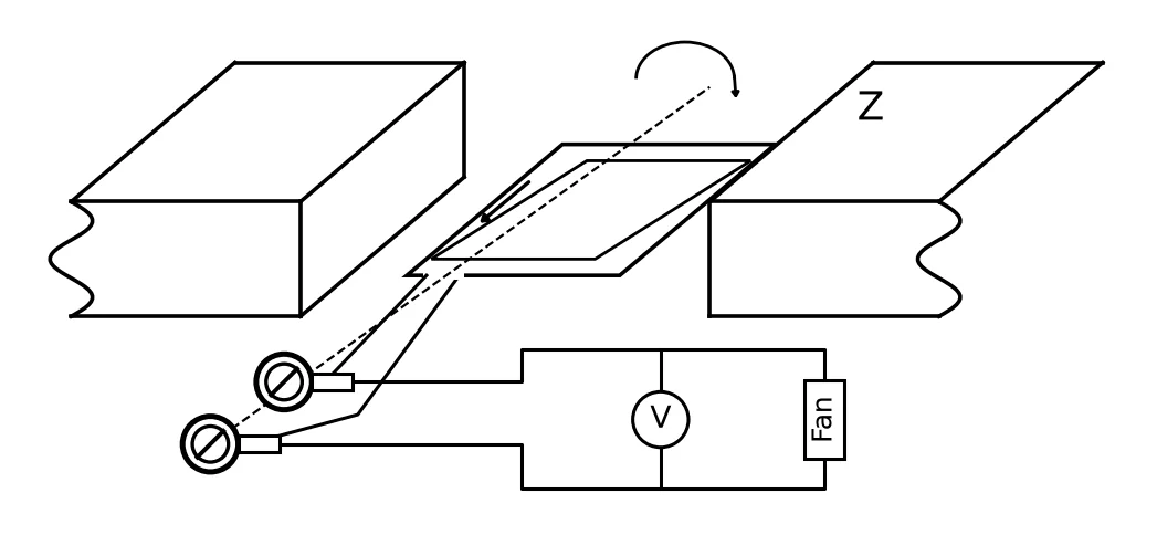 The voltage versus time graph for this generator is given below.
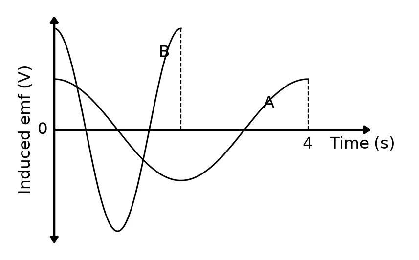
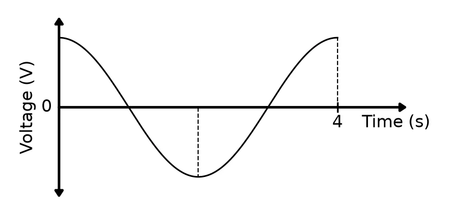 9.4 Redraw this graph in the ANSWER BOOK and label it as A. On the same set of axes, draw the graph for ONE rotation of the coil when the speed of rotation is doubled. Label this as graph B.(3)
Show the memo (3 ticks)Memo
- ✓AmplitudeThe amplitude of graph B is bigger than that of graph A.
1 mark · Describe generators and motors
- ✓PeriodThe period of B is half of A (one cycle ends at s).
1 mark · Describe generators and motors
- ✓ShapeCorrect shape and one cycle (cosine graph): B starts at its maximum, like A.
1 mark · Describe generators and motors
- ✓
5. Question 9.7 · November 2024 · Paper 1 · National (DBE) · 2 marks
The graph below shows how the induced current in a generator varies with time.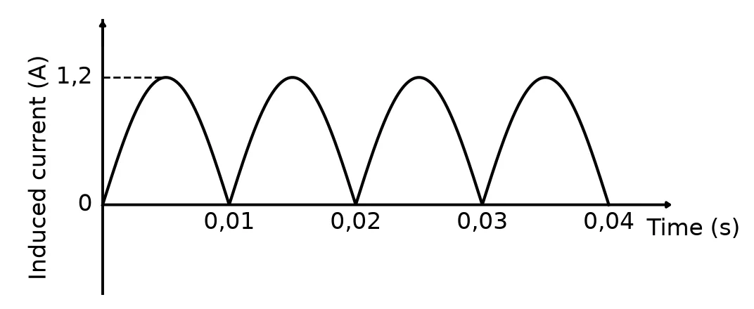 The graph below shows how the induced current varies with time after a change was made to the operation of the generator.
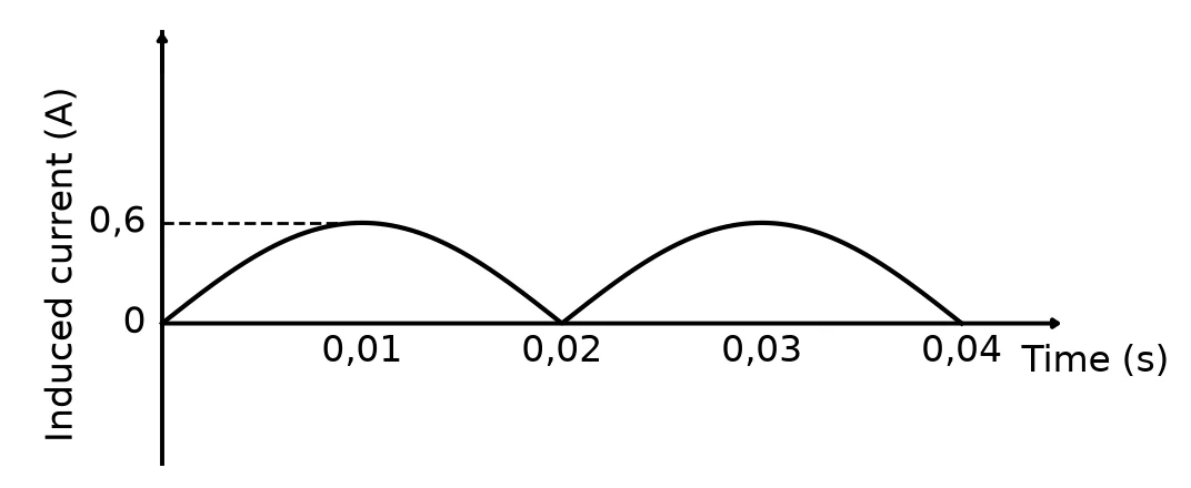 9.7 Fully describe the change that was made.(2)
Show the memo (1 tick)Memo
- ✓Change madeSpeed of rotation halved
Accept: Frequency was halved / Period was doubled2 marks · Describe generators and motors
- ✓
6. Question 9.6 · May/June 2024 · Paper 1 · National (DBE) · 4 marks
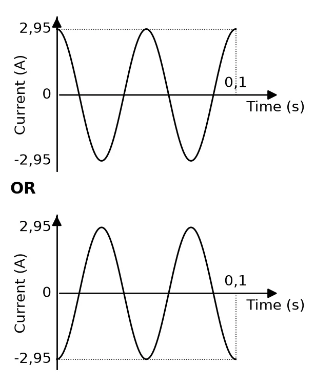
The simplified diagram below represents an AC generator with a coil rotating clockwise. X and Y are two points in the external circuit.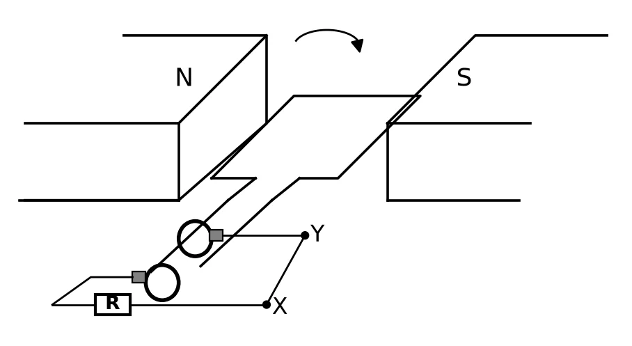 The generator induced current at a frequency of Hz. The coil started rotating from the initial position, as shown in the diagram above.9.6 Sketch a graph of induced current versus time for two complete rotations of the coil.
Indicate the following on the graph:
• The time taken for two rotations
• The maximum current induced by the generator(4)Show the memo (4 ticks)Memo
- ✓Two complete cyclesThe graph shows two complete cycles of the alternating current.
1 mark · Describe generators and motors
- ✓Time for two rotationsGraph stops at s OR one cycle in s.
1 mark · Describe generators and motors
- ✓Maximum current indicatedMaximum current (/ A) as a positive or negative value correctly indicated.
1 mark · Describe generators and motors
- ✓Correct shape (cosine graph)The graph starts at a maximum (positive or negative) value: a cosine graph.
1 mark · Describe generators and motors
- ✓
Free on Android
Know exactly which skill is costing you marks.
Mark past papers tick by tick in the NavyBlue app. It remembers every mark you lose, shows you the skills to fix first, and picks your next questions.
Get NavyBlue free on Google Play